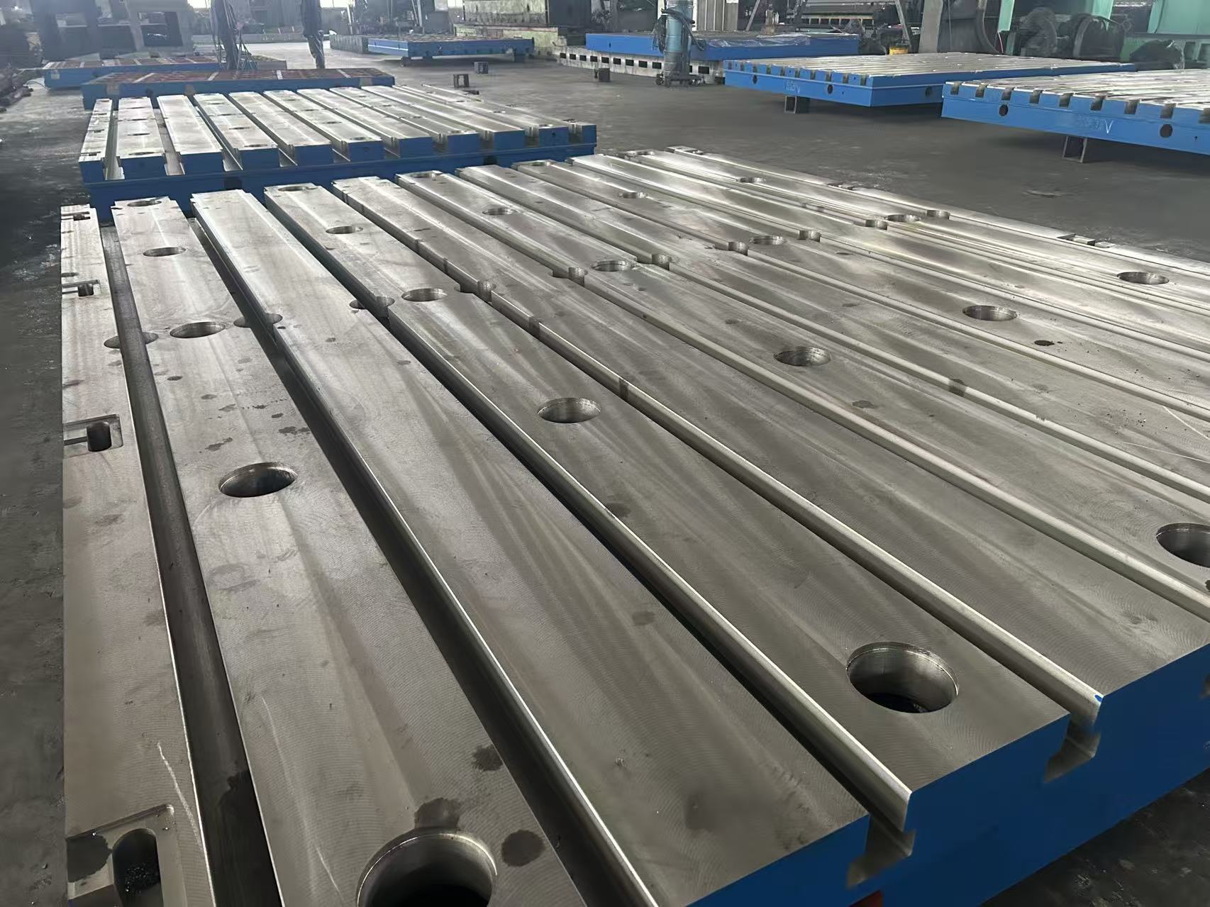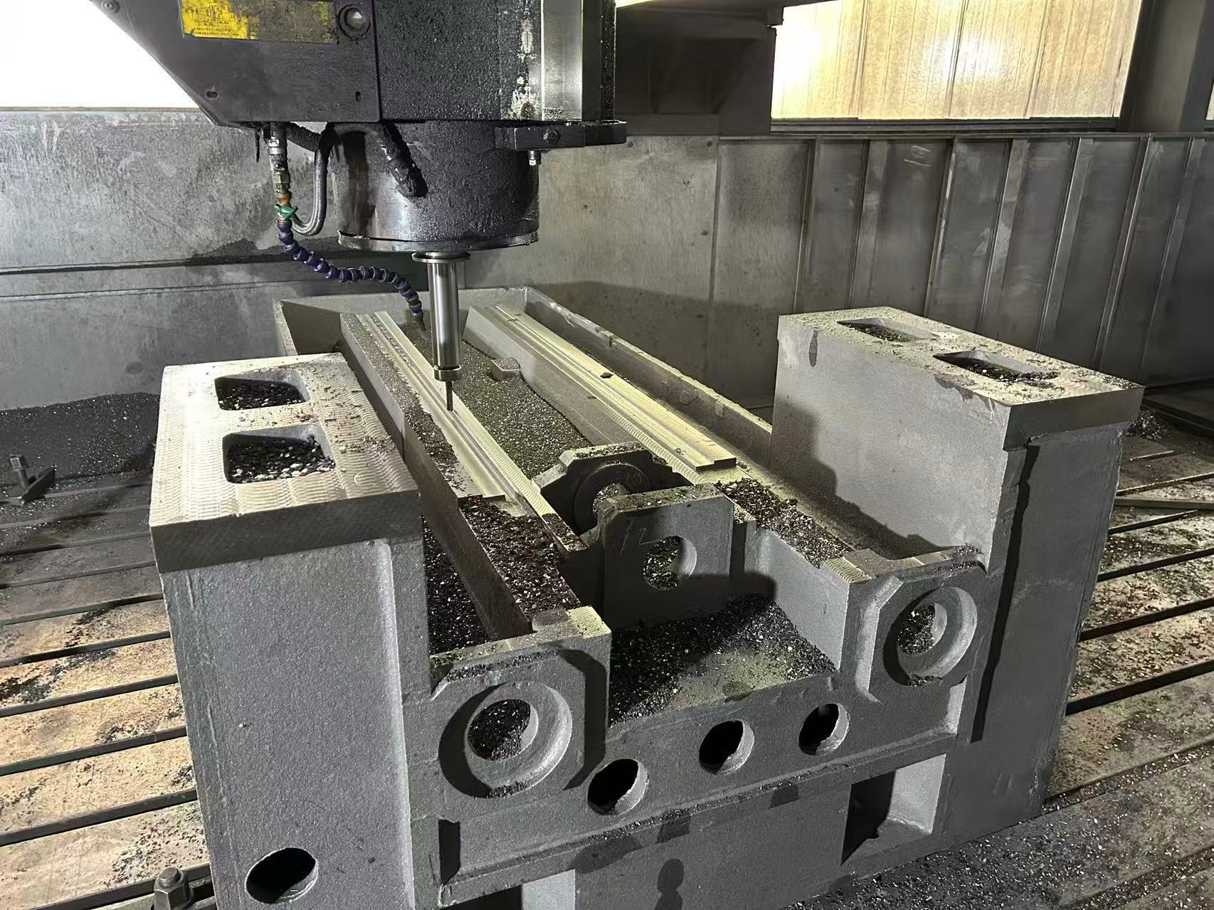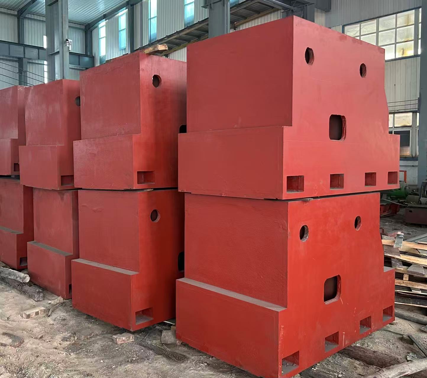
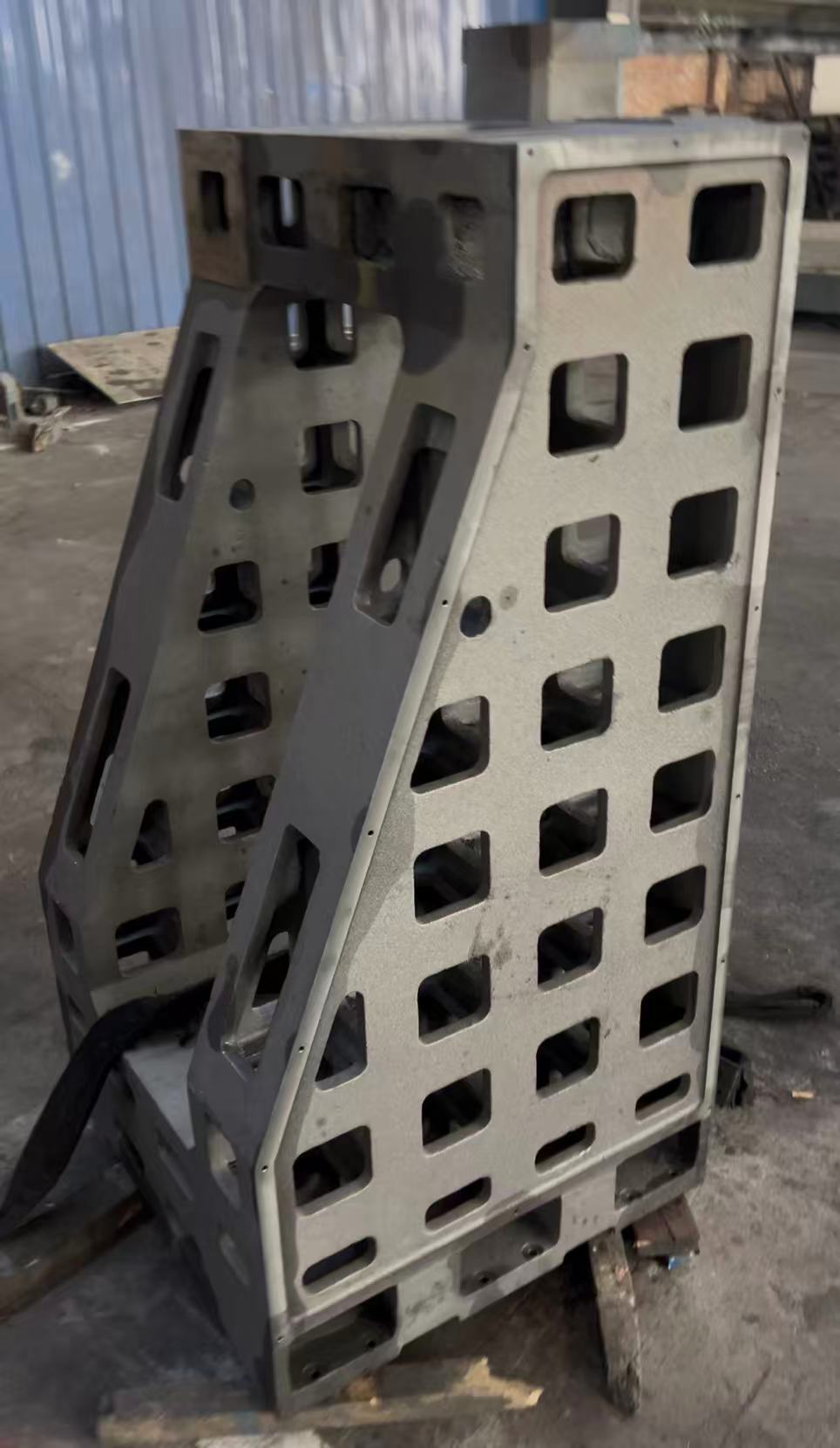
This cast iron machine tool column and large-scale industrial equipment support frame is specifically designed for vertical machining centers, gantry milling machines, CNC boring machines, metallurgical rolling mills, wind turbine main frames, and other equipment. With “vertical precision control + ultra-load-bearing support + cast iron material enhancement” as the core, it overcomes the four major pain points of traditional support structures: “rapid vertical precision attenuation, insufficient load-bearing leading to easy bending, poor vibration resistance affecting equipment performance, and difficulty in installing large-scale frames”.
High-quality materials are carefully selected, including QT500-7/QT600-3 ductile iron (the main material for machine tool columns), HT350-HT400 gray cast iron (for conventional support), and QT700-2 ductile iron (for ultra-heavy-duty frames). Through processes such as “CNC milling + guideway precision grinding + ultra-long aging treatment”, the verticality of machine tool columns is ≤0.002mm/m, the straightness of guideways is ≤0.003mm/m, the load-bearing capacity of large-scale support frames is 50-200 tons, the vertical settlement is ≤0.005mm per year, and the long-term precision attenuation rate of the entire structure is ≤0.05% per year.
It covers industries such as machine tool manufacturing, metallurgy, wind power, and heavy machinery. It helps to increase the movement precision of machine tool spindle boxes by 40%, improve the operational stability of large-scale equipment by 60%, and shorten the installation and commissioning cycle by 35%.
◦ 工作機械用立柱(QT500-7/QT600-3球状黒鉛鋳鉄):引張強度はQT500-7で≥500MPa、QT600-3で≥600MPa、曲げ強度はそれぞれ≥700MPa/800MPaで、優れた疲労耐久性を備えています(主軸台の上下運動による衝撃を10⁶回にわたって耐えることが可能)。30トンの荷重を支えた際の垂直変形は≤0.001mm/mです。また、ガイドウェイ表面にはオプションで焼入れ処理(硬度50~55HRC)を施すことができ、摩耗耐性を倍増させることで、立形マシニングセンターやCNCボーリングマシンなど、高精度な案内が求められる用途にも適しています。
◦ Large-Scale Industrial Equipment Support Frames (HT400/QT600-3/QT700-2): For conventional vertical load-bearing (50-100 tons), HT400 is selected (its shock absorption coefficient is 3-5 times that of steel, absorbing equipment vibration). For heavy-duty load-bearing (100-150 tons), QT600-3 is chosen. For ultra-heavy-duty (150-200 tons, such as rolling mill housings and wind turbine main frames), QT700-2 is adopted (with a tensile strength of ≥700MPa and an elongation of ≥2%). The frame material must have the ability to resist wind loads and temperature deformation, and anti-corrosion coating treatment can be selected for outdoor scenarios (wind power).
◦ Machine Tool Columns: The “integral casting” method is adopted (to avoid vertical deviation caused by splicing). The “resin sand molding + step pouring” process is used to reduce internal defects (defect rate ≤0.3%). After 90-120 days of natural aging + 2 times of artificial aging (holding at 550-600℃ for 8 hours), more than 99.5% of internal stress is eliminated, preventing the column from “lateral bending” due to stress release during long-term use (vertical precision attenuation ≤0.01mm/m in 10 years). The guideway surface undergoes “rough milling – semi-finish milling – finish milling – grinding”, with a straightness of ≤0.003mm/m and a surface roughness of Ra≤0.8μm.
◦ Large-Scale Support Frames: For ultra-large-scale frames (height ≥5m), the “block casting + on-site splicing” method is used. The splicing surfaces are provided with spigot positioning (tolerance H7/h6), and high-strength bolts (M40-M60, Grade 12.9) are used. The verticality after splicing is ≤0.008mm/m. The installation surface undergoes “finish milling – lapping”, with a flatness of ≤0.01mm/1000mm, ensuring the positioning accuracy with the top/bottom of the equipment.
◦ Rectangular Guideways: Suitable for heavy-duty spindle boxes (weight ≤30 tons), the width of the guideway surface is 80-200mm, the verticality is ≤0.002mm/m, the contact area with the slider is ≥90%, and the up-and-down movement precision of the spindle box is ≤0.002mm/1000mm (such as the Z-axis of vertical machining centers).
◦ ドヴェルト案内面:コンパクトな構造で、小型・中型の柱に適しています。ドヴェルト角は55°/60°、インサートによる隙間の微調整が可能で、案内精度は≤0.003mm/m。スペース制約のある場面にも対応できます(例:CNCボーリングマシンの柱など)。
◦ Double Guideway Symmetrical Layout: Large gantry milling machine columns (height ≥3m) adopt a “double rectangular guideway symmetrical design” with a spacing of 200-500mm. The anti-overturning moment is increased by 80%, preventing the column from “unilateral stress bending” when the spindle box moves, and ensuring the beam movement precision is ≤0.005mm/2000mm.
◦ The periphery of the guideway surface adopts “local thickening + quenching” (quenching depth 2-5mm) to improve the local compressive strength (≥250MPa), preventing guideway depression caused by long-term stress (service life ≥100,000 hours).
柱側面には、格子目盛取り付け用溝(幅15~30mm、深さ5~10mm)およびスピンドル冷却水路(口径15~25mm)を備え、二次加工を必要とせず精密なフィードバックと放熱ニーズに対応し、組立誤差の低減を図っています。
◦ Conventional Support Frames (height 3-5m): Adopt a “box-type main structure + cross-shaped reinforcing ribs” (rib spacing 200-300mm). For example, a rolling mill support frame (size 3000×2000×5000mm) has a deformation of ≤0.003mm/m when vertically bearing 100 tons, and the bending stiffness is increased by 70%.
◦ Ultra-Heavy-Duty Frames (such as wind turbine main frame supports, height ≥8m): Adopt a “box-type structure + honeycomb-shaped dense ribs” (rib spacing 150-200mm). When vertically bearing 200 tons, the settlement is ≤0.005mm per year, and it also has the ability to resist wind loads (wind pressure ≤0.7kPa) and earthquakes (seismic intensity ≤8 degrees).
◦ Embedded Installation: Metallurgical rolling mill support frames are embedded into the ground concrete (C30 or above) through anchor bolts (M50-M80, Grade 12.9), and anti-pull anchor bars are set at the bottom to enhance vertical load-bearing stability and prevent the frame from “floating” (anti-pull force ≥500kN).
◦ Adjustable Installation: The bottom of wind power equipment support frames is equipped with heavy-duty leveling pad irons (adjustment range 0-30mm, load-bearing ≤50 tons per set), which can cope with outdoor ground unevenness (horizontal error ≤0.1%), and the verticality after leveling is ≤0.008mm/m.
◦ 上部位置決め対応:フレーム上部には、設備据付用の位置決め穴(公差H7)およびシール溝を設け、圧延機ハウジングや風力タービン主フレームの精密固定に対応しています。位置決め誤差は0.005mm以下で、設備の垂直整合性(同軸度≤0.01mm/1000mm)を保証します。
| コンポーネントカテゴリ | 核心パラメータと構成(鉛直特性強化) |
| 鋳鉄製工作機械用立柱 | 材料:ダクタイル鋳鉄QT500-7/QT600-3;サイズ:高さ1500~5000mm、断面寸法500×500mm~1000×1000mm(幅×厚さ);精度:鉛直度≤0.002mm/m、ガイドウェイ直線度≤0.003mm/m、表面粗さRa≤0.8μm;構造:矩形/ダボ継ぎガイドウェイ、格子スケール溝、冷却水路;耐荷重:垂直方向の耐荷重10~50トン、スピンドルボックスの移動速度≤10m/min |
| 大規模産業設備用支持フレーム | 材料:HT400/QT600-3/QT700-2;サイズ:高さ3000~10000mm、断面寸法1000×1000mm~2000×2000mm;精度:鉛直度≤0.008mm/m、据付面の平面度≤0.01mm/1000mm;構造:箱型+十字/ハニカムリブ、アンカーホール、上部位置決め穴;耐荷重:垂直方向の耐荷重50~200トン、風荷重耐性≤0.7kPa |
| 補助アクセサリー | 重荷重対応の水平調整パッドアイロン(調整範囲0~30mm、一組あたりの耐荷重≤50トン);ガイドウェイインサート(耐摩耗性鋳鉄製、隙間調整に適する);防食塗料(屋外環境向け、塩霧耐性≥720時間);高強度接合ボルト(M40~M60、グレード12.9、大型フレームの接合に適する) |
◦ 工作機械立柱:高さ1500~5000mm、断面500×500mm~1000×1000mm、ガイドウェイ形状(矩形/ダブテール)、精度レベル(通常型≤0.003mm/m、精密型≤0.002mm/m)。
◦ 大型フレーム:高さ3000~10000mm、断面1000×1000mm~2000×2000mm、耐荷重50~200トン、設置方法(埋込式/調整式)、環境適応性(屋外/屋内)。
◦ 材質選定:工作機械立柱にはQT500-7/QT600-3、一般フレームにはHT400/QT600-3、超重荷重フレームにはQT700-2を採用。
◦ 工程強化:ガイドウェイ焼入れ(硬度50~55HRC)、超長時間時効処理(精密用途向け120日間)、屋外用防食塗装(フッ素樹脂塗料/亜鉛めっき)。
◦ 設置・調整:精度±0.001mm/mを確保するための調整、水平調整用パッドの設置、大型フレーム向けの継ぎ手補強、ならびに設置報告書の作成。