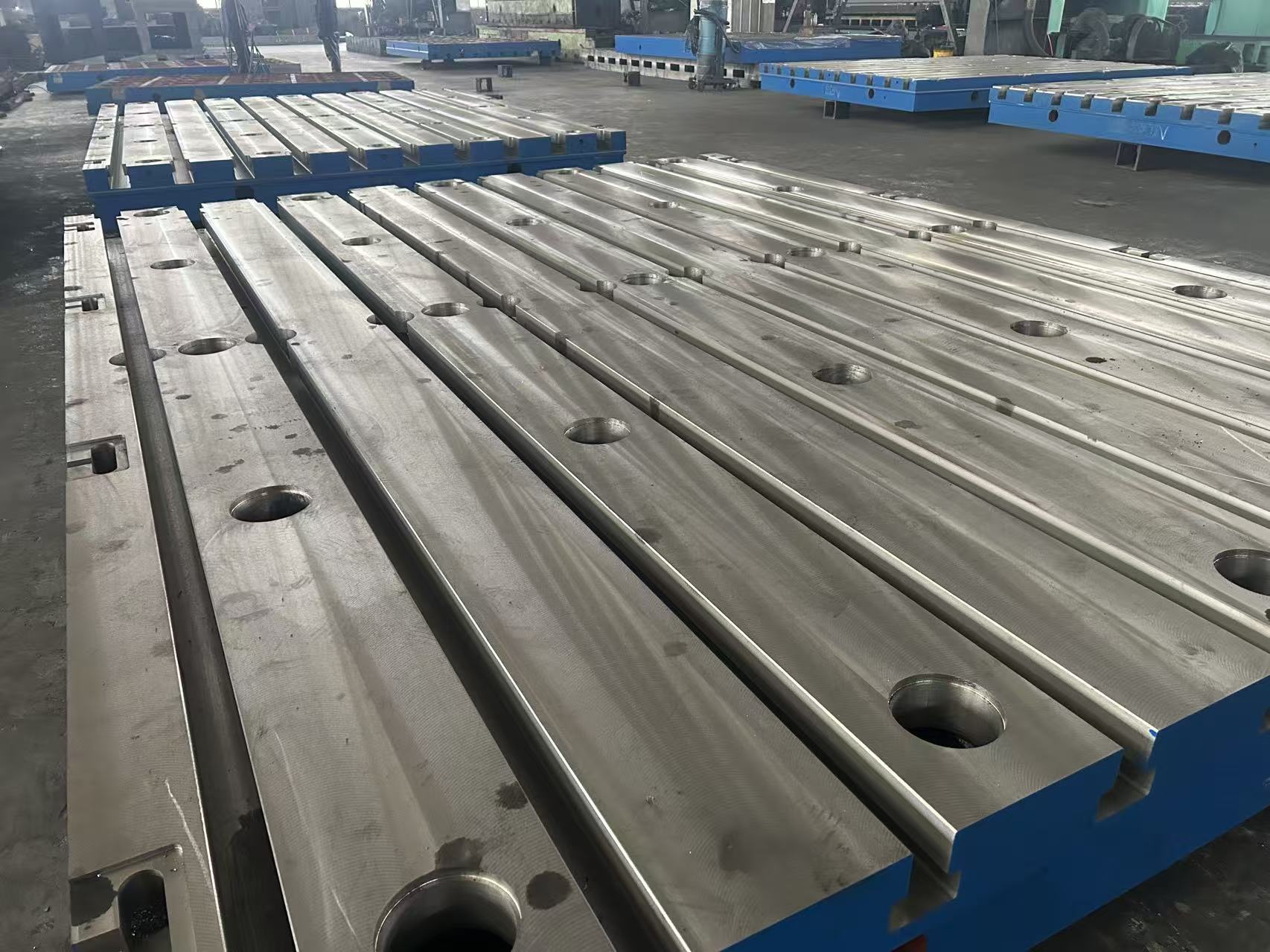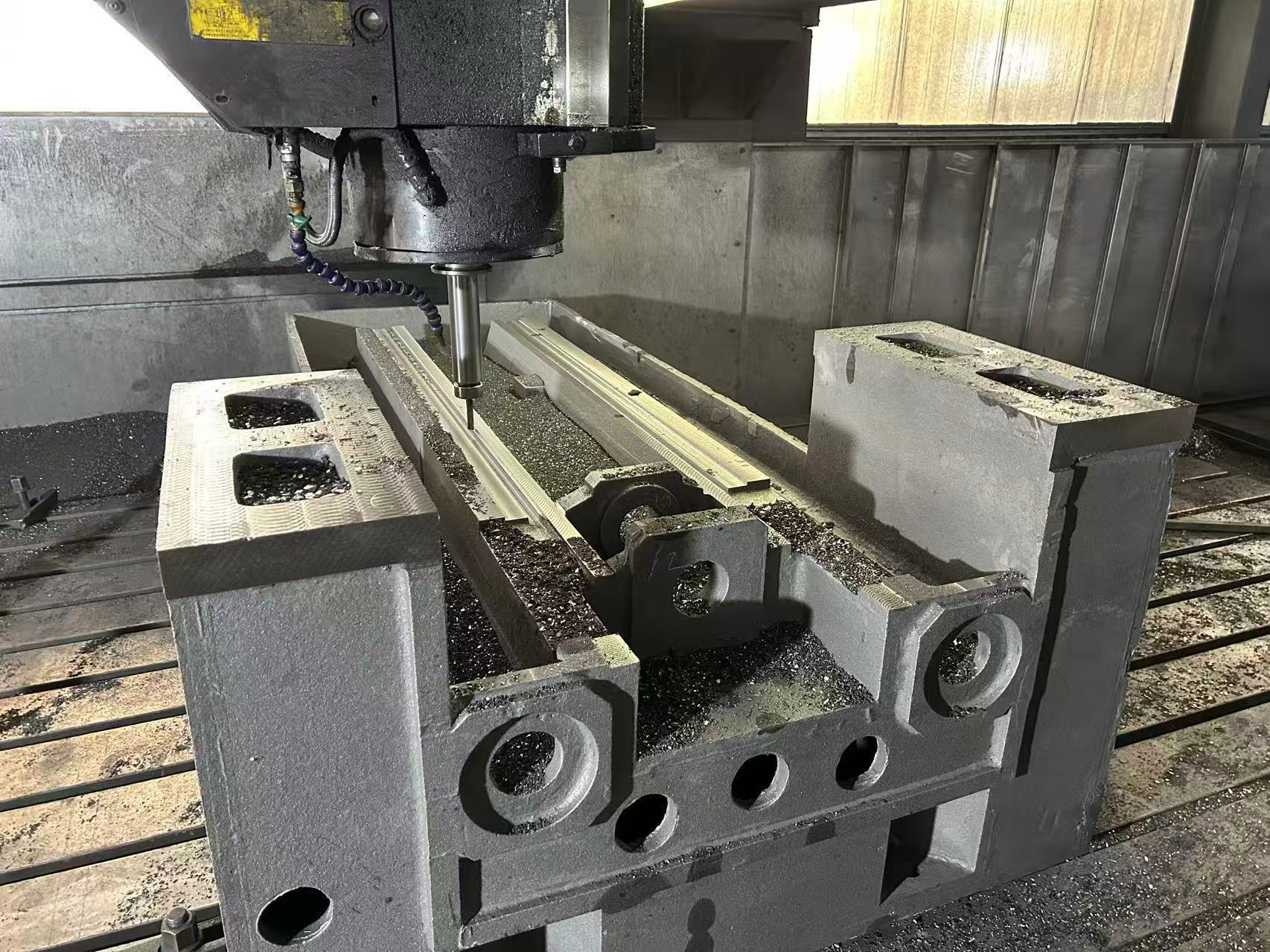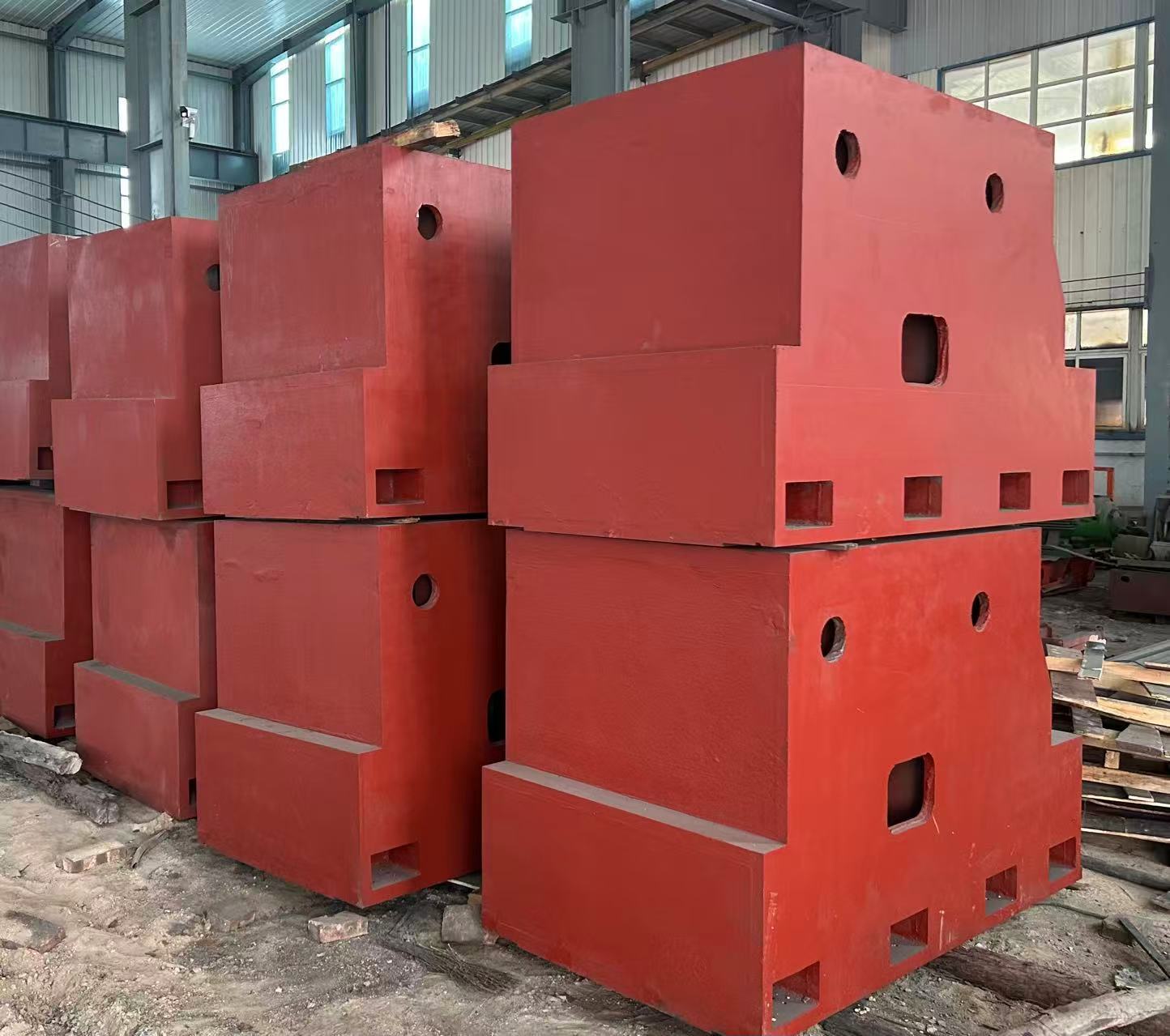
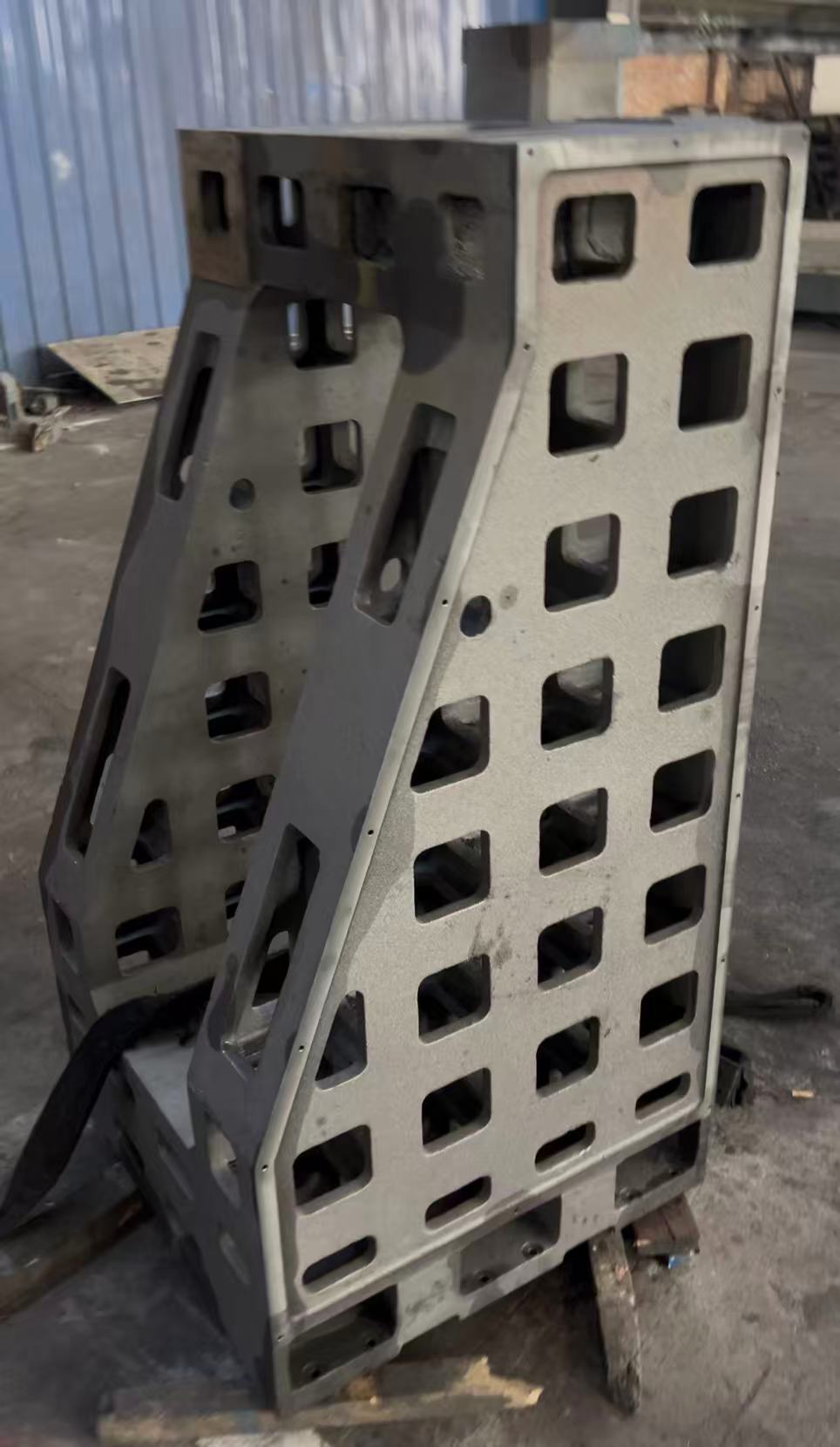
This cast iron machine tool column and large-scale industrial equipment support frame is specifically designed for vertical machining centers, gantry milling machines, CNC boring machines, metallurgical rolling mills, wind turbine main frames, and other equipment. With “vertical precision control + ultra-load-bearing support + cast iron material enhancement” as the core, it overcomes the four major pain points of traditional support structures: “rapid vertical precision attenuation, insufficient load-bearing leading to easy bending, poor vibration resistance affecting equipment performance, and difficulty in installing large-scale frames”.
High-quality materials are carefully selected, including QT500-7/QT600-3 ductile iron (the main material for machine tool columns), HT350-HT400 gray cast iron (for conventional support), and QT700-2 ductile iron (for ultra-heavy-duty frames). Through processes such as “CNC milling + guideway precision grinding + ultra-long aging treatment”, the verticality of machine tool columns is ≤0.002mm/m, the straightness of guideways is ≤0.003mm/m, the load-bearing capacity of large-scale support frames is 50-200 tons, the vertical settlement is ≤0.005mm per year, and the long-term precision attenuation rate of the entire structure is ≤0.05% per year.
It covers industries such as machine tool manufacturing, metallurgy, wind power, and heavy machinery. It helps to increase the movement precision of machine tool spindle boxes by 40%, improve the operational stability of large-scale equipment by 60%, and shorten the installation and commissioning cycle by 35%.
◦ 공작기계 기둥(QT500-7/QT600-3 연강철): 인장강도는 QT500-7 기준 ≥500MPa, QT600-3 기준 ≥600MPa이며, 굽힘강도는 각각 ≥700MPa와 ≥800MPa에 달하고, 우수한 피로 강도를 갖추어 스핀들박스의 상하 운동에 의한 충격을 10⁶회까지 견딜 수 있습니다. 30톤의 하중을 지지할 때 수직 변형은 ≤0.001mm/m에 불과합니다. 가이드웨이 표면은 옵션으로 담금처리(경도 50~55HRC)가 가능하여 내마모성이 두 배로 향상되므로, 수직 가공센터나 CNC 보링머신 등 고정밀 가이드가 필요한 경우에도 적합합니다.
◦ Large-Scale Industrial Equipment Support Frames (HT400/QT600-3/QT700-2): For conventional vertical load-bearing (50-100 tons), HT400 is selected (its shock absorption coefficient is 3-5 times that of steel, absorbing equipment vibration). For heavy-duty load-bearing (100-150 tons), QT600-3 is chosen. For ultra-heavy-duty (150-200 tons, such as rolling mill housings and wind turbine main frames), QT700-2 is adopted (with a tensile strength of ≥700MPa and an elongation of ≥2%). The frame material must have the ability to resist wind loads and temperature deformation, and anti-corrosion coating treatment can be selected for outdoor scenarios (wind power).
◦ Machine Tool Columns: The “integral casting” method is adopted (to avoid vertical deviation caused by splicing). The “resin sand molding + step pouring” process is used to reduce internal defects (defect rate ≤0.3%). After 90-120 days of natural aging + 2 times of artificial aging (holding at 550-600℃ for 8 hours), more than 99.5% of internal stress is eliminated, preventing the column from “lateral bending” due to stress release during long-term use (vertical precision attenuation ≤0.01mm/m in 10 years). The guideway surface undergoes “rough milling – semi-finish milling – finish milling – grinding”, with a straightness of ≤0.003mm/m and a surface roughness of Ra≤0.8μm.
◦ Large-Scale Support Frames: For ultra-large-scale frames (height ≥5m), the “block casting + on-site splicing” method is used. The splicing surfaces are provided with spigot positioning (tolerance H7/h6), and high-strength bolts (M40-M60, Grade 12.9) are used. The verticality after splicing is ≤0.008mm/m. The installation surface undergoes “finish milling – lapping”, with a flatness of ≤0.01mm/1000mm, ensuring the positioning accuracy with the top/bottom of the equipment.
◦ Rectangular Guideways: Suitable for heavy-duty spindle boxes (weight ≤30 tons), the width of the guideway surface is 80-200mm, the verticality is ≤0.002mm/m, the contact area with the slider is ≥90%, and the up-and-down movement precision of the spindle box is ≤0.002mm/1000mm (such as the Z-axis of vertical machining centers).
◦ 도브테일 가이드웨이: 컴팩트한 구조로 소형 및 중형 기둥에 적합하며, 도브테일 각도는 55°/60°이고, 인서트를 통해 간극을 세밀하게 조정할 수 있습니다. 가이드 정밀도는 ≤0.003mm/m으로, 공간 제약이 있는 경우에도 활용 가능합니다(예: CNC 보링머신 기둥).
◦ Double Guideway Symmetrical Layout: Large gantry milling machine columns (height ≥3m) adopt a “double rectangular guideway symmetrical design” with a spacing of 200-500mm. The anti-overturning moment is increased by 80%, preventing the column from “unilateral stress bending” when the spindle box moves, and ensuring the beam movement precision is ≤0.005mm/2000mm.
◦ The periphery of the guideway surface adopts “local thickening + quenching” (quenching depth 2-5mm) to improve the local compressive strength (≥250MPa), preventing guideway depression caused by long-term stress (service life ≥100,000 hours).
◦ 기둥 측면에는 그레이팅 스케일 설치 홈(폭 15~30mm, 깊이 5~10mm)과 스핀들 냉각수 통로(구경 15~25mm)를 마련하여, 추가 가공 없이 정밀 피드백 및 열 방출 요구에 적응하도록 설계되어 조립 오차를 줄입니다.
◦ Conventional Support Frames (height 3-5m): Adopt a “box-type main structure + cross-shaped reinforcing ribs” (rib spacing 200-300mm). For example, a rolling mill support frame (size 3000×2000×5000mm) has a deformation of ≤0.003mm/m when vertically bearing 100 tons, and the bending stiffness is increased by 70%.
◦ Ultra-Heavy-Duty Frames (such as wind turbine main frame supports, height ≥8m): Adopt a “box-type structure + honeycomb-shaped dense ribs” (rib spacing 150-200mm). When vertically bearing 200 tons, the settlement is ≤0.005mm per year, and it also has the ability to resist wind loads (wind pressure ≤0.7kPa) and earthquakes (seismic intensity ≤8 degrees).
◦ Embedded Installation: Metallurgical rolling mill support frames are embedded into the ground concrete (C30 or above) through anchor bolts (M50-M80, Grade 12.9), and anti-pull anchor bars are set at the bottom to enhance vertical load-bearing stability and prevent the frame from “floating” (anti-pull force ≥500kN).
◦ Adjustable Installation: The bottom of wind power equipment support frames is equipped with heavy-duty leveling pad irons (adjustment range 0-30mm, load-bearing ≤50 tons per set), which can cope with outdoor ground unevenness (horizontal error ≤0.1%), and the verticality after leveling is ≤0.008mm/m.
◦ 상부 위치 맞춤 기능: 프레임 상부에는 설비 설치용 정위치 홀(H7 공차)과 밀봉 홈이 마련되어 있어 압연기 하우징 및 풍력터빈 메인프레임의 정밀 고정에 적합합니다. 위치 오차는 ≤0.005mm로, 설비의 수직 정렬(동축성 ≤0.01mm/1000mm)을 보장합니다.
| 부품 카테고리 | 핵심 파라미터 및 구성(수직 특성 강화) |
| 주철 제작 공작기계 칼럼 | 재질: QT500-7/QT600-3 연성철; 규격: 높이 1500~5000mm, 단면 500×500mm~1000×1000mm(폭×두께); 정밀도: 수직도 ≤0.002mm/m, 가이드웨이 직선도 ≤0.003mm/m, 표면 거칠기 Ra≤0.8μm; 구조: 직사각형/도베이트 가이드웨이, 그레이팅 스케일 홈, 냉각수 통로; 내하중: 수직 하중 10~50톤, 스핀들 박스 이동 속도 ≤10m/min |
| 대규모 산업 설비 지지 프레임 | 재질: HT400/QT600-3/QT700-2; 규격: 높이 3000~10000mm, 단면 1000×1000mm~2000×2000mm; 정밀도: 수직도 ≤0.008mm/m, 설치면 평탄도 ≤0.01mm/1000mm; 구조: 박스형 + 크로스/벌집형 리브, 앵커홀, 상부 정위치 홀; 내하중: 수직 하중 50~200톤, 풍하중 저항력 ≤0.7kPa |
| 보조 액세서리 | 중량형 레벨링 패드 철제(조절 범위 0~30mm, 단일 세트당 내하중 ≤50톤); 가이드웨이 삽입물(내마모성 주철 소재, 간극 조절 용이); 내부식 코팅(야외 환경용, 염분 분무 내성 ≥720시간); 고강도 접합 볼트(M40~M60, 강도 등급 12.9, 대형 프레임 접합용) |
◦ 공작기계 기둥: 높이 1500~5000mm, 단면 500×500mm~1000×1000mm, 가이드웨이 형식(직사각형/도베이트), 정밀도 수준(일반형 ≤0.003mm/m, 정밀형 ≤0.002mm/m).
◦ 대형 프레임: 높이 3000~10000mm, 단면 1000×1000mm~2000×2000mm, 하중 지지력 50~200톤, 설치 방식(매립형/조절형), 환경 적응(실외/실내).
◦ 재료 선택: 공작기계 기둥에는 QT500-7/QT600-3, 일반형 프레임에는 HT400/QT600-3, 초중량급 프레임에는 QT700-2를 사용합니다.
◦ 공정 개선: 가이드웨이 담금질(경도 50~55HRC), 초장기 노화처리(120일, 정밀 시나리오용), 실외용 방식 코팅(불소 도료/아연도금).
◦ 설치 및 시운전(정밀도 ±0.001mm/m), 수평 조정용 패드 철제 설치, 대형 프레임의 경우 이음부 가이드 작업 수행 및 설치 보고서 제공;